Temperature and resistance are only part of the equation.
A gasket material suitability is defined by a variety of application factors shown in the adjacent diagram. The common perception that the temperature and chemical resistance must be assured are only part of the equation. Amorim Cork Composites systems' approach ensures joint integrity by considering the multiple variables that are involved.
Flange & Sealing Area
Proper Flange & Gasket Design
Gasket compression design by application of spaced fasteners is also a function of plate thickness, acceptable gasket pressures, gasket performance under compression, and flange dimensions. Maximum gasket deflection occurs at the location where the fastener applies force. 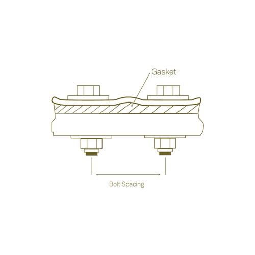
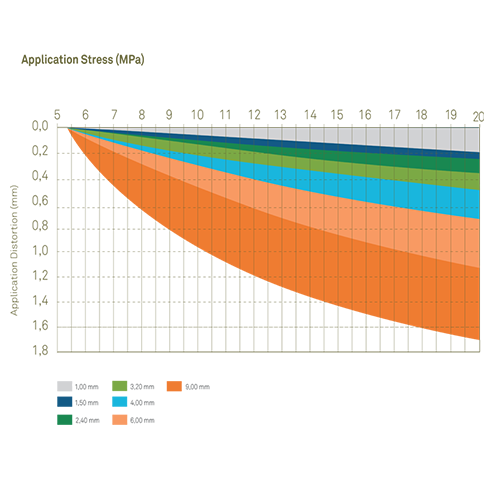
The amount of bowing or deflection of the cover flange depends on several factors. This effect may be minimized by proper design of the fastener spacing, cover / flange plate thickness and stiffness, and proper selection of gasket materials. Use our application distortion graphs to define the best material thickness for your application.
Temperature and Medium
Adequate Material Selection
Our products are made to proprietary formulas and are only manufactured by Amorim. There are literally infinite possible formulations within each type of polymer and cork, inclusively the blend of polymer types.
A wide range of variations on physical properties like tensile strength, compressibility, and hardness can be found amongst our products made of the same basic elastomer, and these are all factors that usually greatly affect the functionality in the application.Other factors like chemical resistance and temperature range also vary, but normally to a lesser degree.
View our detailed Material Data Sheets for temperature and chemical resistance, or contact us for further information.
Fasteners
Thread standards
ISO metric screw thread is the preferred series and has displaced many older systems. Other common systems include the British Standard Whitworth, BA system (British Association), and the SAE Unified Thread Standard.
ISO metric screw threads are designated by the letter M followed by the major diameter of the thread in millimeters, e.g. M8 x 1.25. For sizes 1/4" diameter and larger, The SAE Unified Thread Standard sizes are designated as 1/4"-20, 1/4"- 28, etc. the first number giving the diameter in inches and the second number being threads per inch. Most thread sizes are available in UNC or UC (Unified Coarse or Unified Fine Thread).
View extensive thread details in the Joint QTOOL.
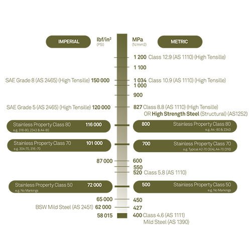
Mechanical classifications
The numbers or shapes stamped on the head of the bolt are referred to as the grade of the bolt and define the strength of a bolt. The international standard for metric screws is defined by ISO 898, SAE J1199 and ASTM F568M. In case of imperial sizes the grade is dictated by the number of radial shapes. ASTM and ISO bolts use integer values to indicate grades.
Assembly Procedure
- Inspect fasteners, nuts, and washers and clean flange surface. Replace any component if necessary.
- Do not use lubricated fasteners unless previously specified by torque evaluation. Evaluate torque using our Joint QTOOL software.
- Use washers under fasteners and nuts where possible • Install new gasket, never reuse old gaskets or use multiple gaskets
- Install fasteners in cross pattern sequence (see below) and hand tighten.
- Optimal uniform fastener tightening is obtained 3 steps until the final torque is achieved, following the cross pattern sequence for every step.
Would you like to know more about this subject?
Let us know your details and we'll get back to you.